Pete Askew
Admin
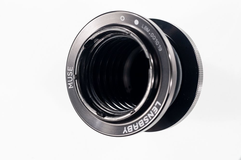
The later Lensbaby series of lenses introduced an OpticSwap system whereby the optics contained by the various bodies could be changed to alter the charactaristics of the lens. The elements are stored in containers the lids of which are also the tool used to swap the elements over. The lens body has a female bayonet fitting into which the lens element drops and male lugs that locate the outer ring of the optic. This cannot be seen when the optic is attached as the outer ring of the optic covers it, but the male tabs on the optic and the female cutouts into which they locate are spaced uniformly beteen the three cutouts visible on the outer ring of the optic.
The underside to the lid has three tabs that engage with the three cutouts on the optic and allow cast-in pins on the body be depressed slightly against a 'spring' below them thus allowing the optic to be rotated to engage with the bayonet (anti-clockwise to remove, clockwise to fit). The spring is actually just a slit in the plastic below each of the lugs on the lens body and only needs to be deformed slightly to allow the optic to be rotated.
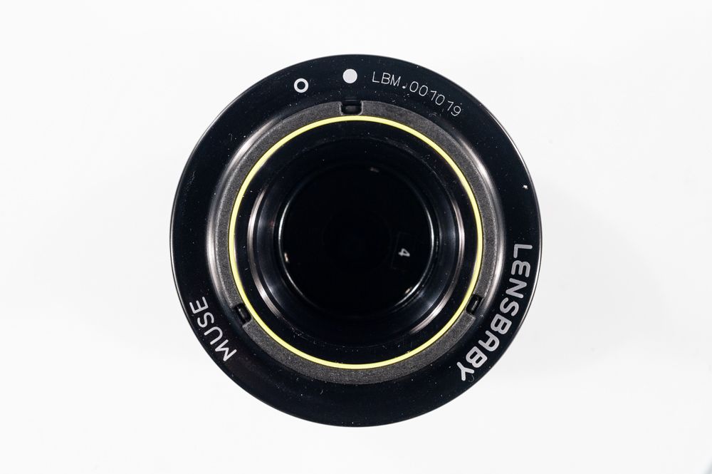
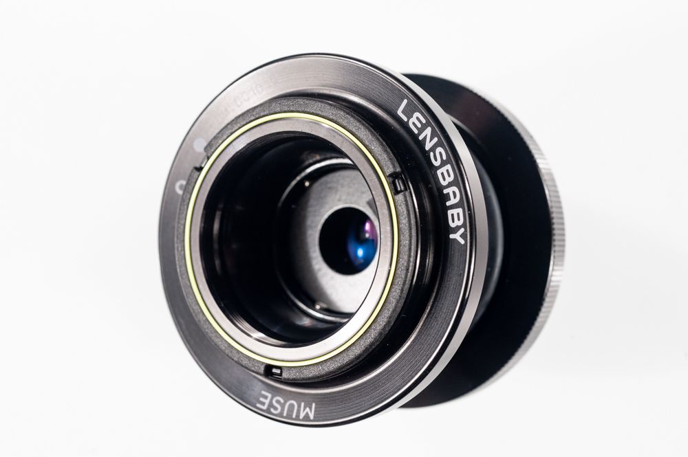
These images shows a Lensbaby Muse with an optic fitted. You can see the cutouts in the optic element (grey ring) with the cast-in pins of the body within each: these are the pins that need to be depressed to allow the optic to be rotated withing the bayonet fitting.
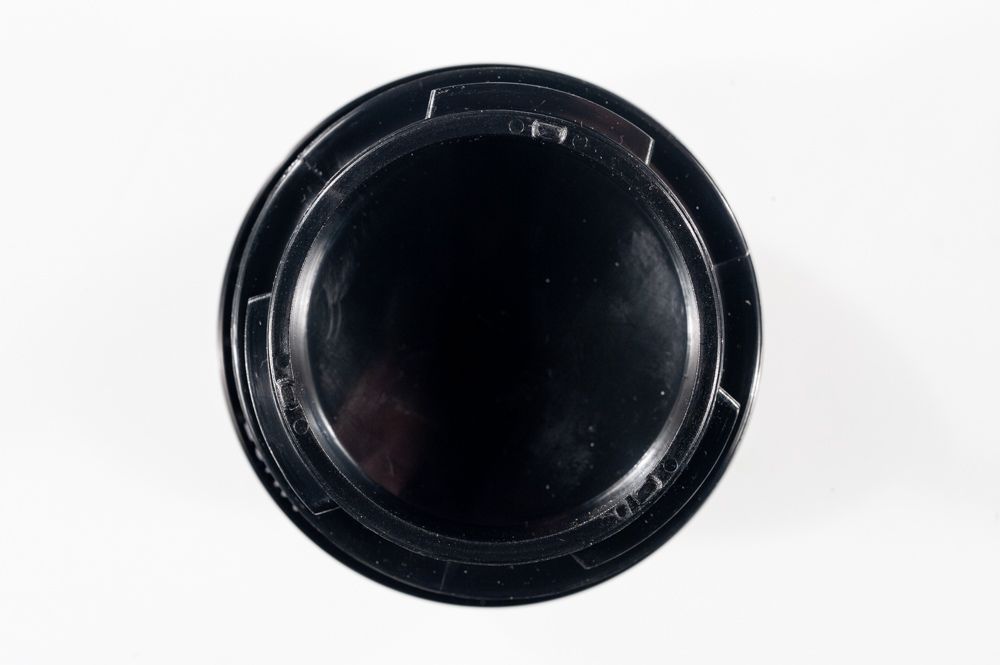
These images show the underside of the lid / optic removal tool.
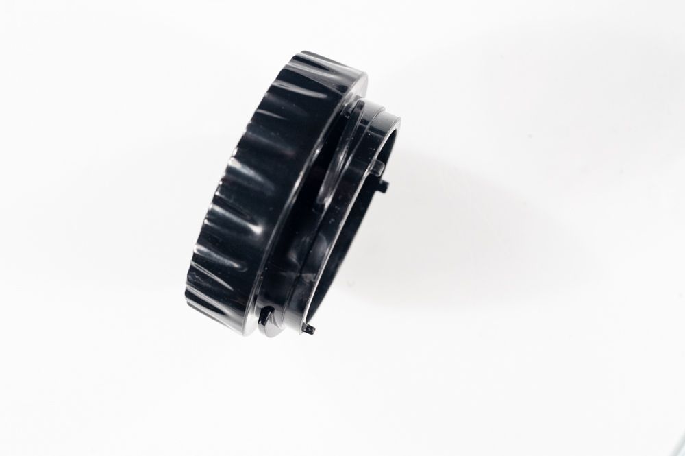
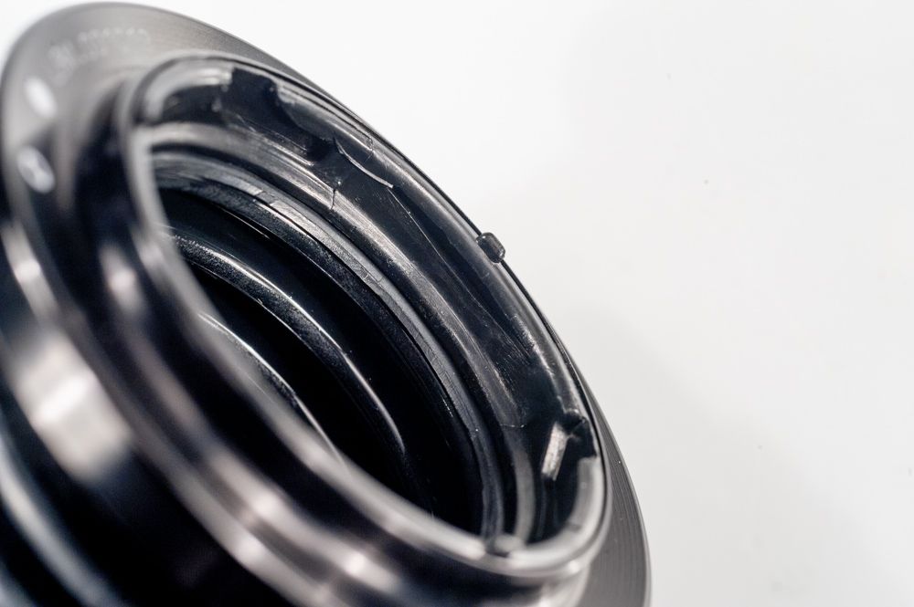
Once removed one can see the bayonet and also see clearer how the mechanism works.
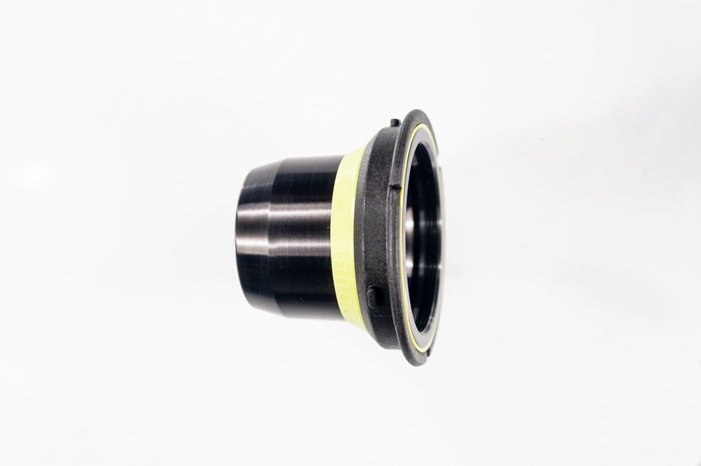
The lens body
The optic (showing two of the male tabs and a cutout)
This shows the 'spring' below a pin on the body.
I tried to remove an optic without the tool and couldn't by simply trying to depress the pins one at a time. I even couldn't using a lens pin-tool and a screwdriver as the belows compress and prevent one applying pressure uniformly (holding the upper body in a vice might have worked). However, looking at the dimensions of the body and optic it should be simple to make a tool from a piece of 50 mm diameter drain pipe (ISO). This has an outer diameter of 50 mm and usually a wall thickness of 2 mm and so could be formed to make a tool (or one could buy an optic in its container!).
By the way, the bellows appear to be fitted to the front of the body by being trapped between the front plate and an insert that probably snaps in from the rear. If the bellows have come away, it should be possible to 'pop' the ring out and reassemble the lens.
The underside to the lid has three tabs that engage with the three cutouts on the optic and allow cast-in pins on the body be depressed slightly against a 'spring' below them thus allowing the optic to be rotated to engage with the bayonet (anti-clockwise to remove, clockwise to fit). The spring is actually just a slit in the plastic below each of the lugs on the lens body and only needs to be deformed slightly to allow the optic to be rotated.
These images shows a Lensbaby Muse with an optic fitted. You can see the cutouts in the optic element (grey ring) with the cast-in pins of the body within each: these are the pins that need to be depressed to allow the optic to be rotated withing the bayonet fitting.
These images show the underside of the lid / optic removal tool.
Once removed one can see the bayonet and also see clearer how the mechanism works.
The lens body
The optic (showing two of the male tabs and a cutout)
This shows the 'spring' below a pin on the body.
I tried to remove an optic without the tool and couldn't by simply trying to depress the pins one at a time. I even couldn't using a lens pin-tool and a screwdriver as the belows compress and prevent one applying pressure uniformly (holding the upper body in a vice might have worked). However, looking at the dimensions of the body and optic it should be simple to make a tool from a piece of 50 mm diameter drain pipe (ISO). This has an outer diameter of 50 mm and usually a wall thickness of 2 mm and so could be formed to make a tool (or one could buy an optic in its container!).
By the way, the bellows appear to be fitted to the front of the body by being trapped between the front plate and an insert that probably snaps in from the rear. If the bellows have come away, it should be possible to 'pop' the ring out and reassemble the lens.
")